Raspberry GPIO
GPIO stands for General Purpose Input Output.
The Raspberry Pi 40 GPIO pins, which are connections between the Raspberry Pi, and the real world.
- Output pins are like switches that the Raspberry Pi can turn on or off. These have limited power so the idea is usually to use them as signaling conectors to external devices (that have its own power supply.)
- Input pins are like switches that you can turn on or off from the outside world used to collect data from a sensor, or a signal from another device.
Overview

The Broadcom datasheet linked from raspberrypi.org in Boštjan Jerko answer is a great reference; for example, section 6.2 describes the various functions that can be assigned to each pin as per joan's answer. To summarize the meaning of the ones indicated on your card:
I2C, SDA & SCL: In the Broadcom datasheet these are only mentioned directly in that section 6.2 table, but they are for an I2C bus, which is discussed in the section on the BSC (Broadcom serial controller). The 'DA' in SDA stands for data, the 'CL' in SCL stands for clock; the S stands for serial. You can do more reading about the significance of the clock line for various types of computer bus, but you do not have to understand it on that level to use it -- as joan says, there are programming libraries that abstract that away. You will probably find I2C devices that come with their own userspace drivers and the linux kernel includes some as well. Most computers have an I2C bus, presumably for some of the purposes listed by wikipedia, such as interfacing with the RTC (real time clock) and configuring memory. However, it is not exposed, meaning you can't attach anything else to it, and there are a lot of interesting things that could be attached -- pretty much any kind of common sensor (barometers, accelerometers, gyroscopes, luminometers, etc.) as well as output devices and displays. You can buy a USB to I2C adapter for a normal computer, but they cost a few hundred dollars. You can attach multiple devices to the exposed bus on the pi.
UART, TXD & RXD: This is a traditional serial line; for decades most computers have had a port for this and a port for parallel.1 Some pi oriented OS distros such as Raspbian by default boot with this serial line active as a console, and you can plug the other end into another computer and use some appropriate software to communicate with it. Note this interface does not have a clock line; the two pins may be used for full duplex communication (simultaneous transmit and receive).
PCM, CLK/DIN/DOUT/FS: PCM is is how uncompressed digital audio is encoded. The data stream is serial, but interpreting this correctly is best done with a separate clock line (more lowest level stuff).
SPI, MOSI/MISO/CE0/CE1: SPI is a serial bus protocol serving many of the same purposes as I2C, but because there are more wires, it can operate in full duplex which makes it faster and more flexible.
Serial Interface Peripheral (SPI)
This Serial interface peripheral supports the following features: • Implements a 3 wire serial protocol, variously called Serial Peripheral Interface (SPI) or Synchronous Serial Protocol (SSP). • Implements a 2 wire version of SPI that uses a single wire as a bidirectional data wire instead of one for each direction as in standard SPI. • Implements a LoSSI Master (Low Speed Serial Interface) • Provides support for polled, interrupt or DMA operation.
A serial peripheral interface (SPI compatible) is supported to enable high speed communication to the host. The SPI Interface can handle data speed of up to 10 Mbit/s.
UART
The internal UART interface is compatible to an RS232 serial interface. The default transfer speed is 9.6 kbit/s.
I2C Bus Interface
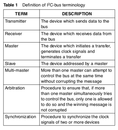
An Inter IC (I2C) bus interface is supported to enable a low cost, low pin count serial bus interface to the host. Philips developed a simple bi-directional 2-wire bus for efficient inter-IC control. This bus is called the Inter IC or I2C-bus.
Here are some of the features of the I2C-bus:
- Only two bus lines are required;a serial data line(SDA) and a serial clock line (SCL)
- Each device connected to the bus is software addressable by a unique address and simple master/slave relationships exist at all times; masters can operate as master-transmitters or as master-receivers
- It’s a true multi-master bus including collision detection and arbitration to prevent data corruption if two or more masters simultaneously initiate data transfer
- Serial,8-bit oriented,bi-directional data transfers can be made at up to 100 kbit/s in the Standard-mode, up to 400 kbit/s in the Fast-mode, or up to 3.4 Mbit/s in the High-speed mode
- On-chip filtering rejects spikes on the bus data line to preserve data integrity The number of ICs that can be connected to the same bus is limited only by a maximum bus capacitance of 400 pF.
BIT TRANSFER The data on the SDA line must be stable during the HIGH period of the clock. The HIGH or LOW state of the data line can only change when the clock signal on the SCL line is LOW
Source THE I2C-BUS SPECIFICATION VERSION 2.1 JANUARY 2000 - i2c_spec.pdf
