Light Sensor
LDR
Types of photo resistors and working mechanisms
Based on the materials used, photo resistors can be divided into two types; intrinsic and extrinsic.
- Intrinsic photo resistors use undoped materials such as silicon or germanium. Photons that fall on the device excite electrons from the valence band to the conduction band, and the result of this process are more free electrons in the material, which can carry current, and therefore less resistance.
- Extrinsic photo resistors are made of materials doped with impurities, also called dopants. The dopants create a new energy band above the existing valence band, populated by electrons. These electrons need less energy to make the transition to the conduction band thanks to the smaller energy gap. The result is a device sensitive to different wavelengths of light. Regardless, both types will exhibit a decrease in resistance when illuminated. The higher the light intensity, the larger the resistance drop is. Therefore, the resistance of LDRs is an inverse, nonlinear function of light intensity.
Read more http://www.resistorguide.com/photoresistor/
Latency
Another interesting property of photo resistors is that there is time latency between changes in illumination and changes in resistance. This phenomenon is called the resistance recovery rate. It takes usually about 10 ms for the resistance to drop completely when light is applied after total darkness, while it can take up to 1 second for the resistance to rise back to the starting value after the complete removal of light. For this reason the LDR cannot be used where rapid fluctuations of light are to be recorded or used to actuate control equipment, but this same property is exploited in some other devices, such as audio compressors, where the function of the light dependent resistor is to smooth the response.
Read more http://www.resistorguide.com/photoresistor/
CdS
The popular cadmium sulfide types are often indicated as CdS photoresistors.

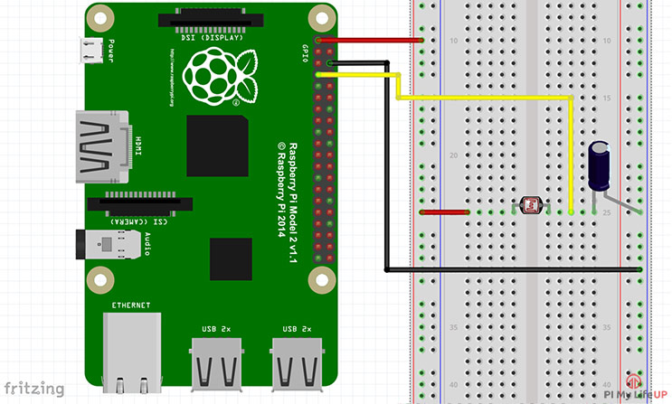
Circuit
In the light, this sensor will have a resistance of only a few hundred ohms while in the dark, it can have a resistance of several megohms.
The capacitor in our circuit is there, so we’re able to measure the resistance of the LDR sensor. A capacitor essentially acts like a battery charging up while receiving power and then discharging when no longer receiving power. Using this in series with the LDR, we can work out how much resistance the LDR is giving out thus whether it is light or dark.

the code
#!/usr/local/bin/python

import RPi.GPIO as GPIO
import time

GPIO.setmode(GPIO.BOARD)

#define the pin that goes to the circuit
pin_to_circuit = 7

def rc_time (pin_to_circuit):
    count = 0

    #Output on the pin for
    GPIO.setup(pin_to_circuit, GPIO.OUT)
    GPIO.output(pin_to_circuit, GPIO.LOW)
    time.sleep(0.1)

    #Change the pin back to input
    GPIO.setup(pin_to_circuit, GPIO.IN)

    #Count until the pin goes high
    while (GPIO.input(pin_to_circuit) == GPIO.LOW):
        count += 1

    return count

#Catch when script is interrupted, cleanup correctly
try:
    # Main loop
    while True:
        print rc_time(pin_to_circuit)
except KeyboardInterrupt:
    pass
finally:
    GPIO.cleanup()
Credit https://pimylifeup.com/raspberry-pi-light-sensor/
Sand Alone Circuit
https://www.instructables.com/id/How-to-Make-LDR-Darkness-Sensor-Circuit-Simple-DIY/

- LDR
- 50KOHM RESISTOR
- 1KOHM RESISTOR
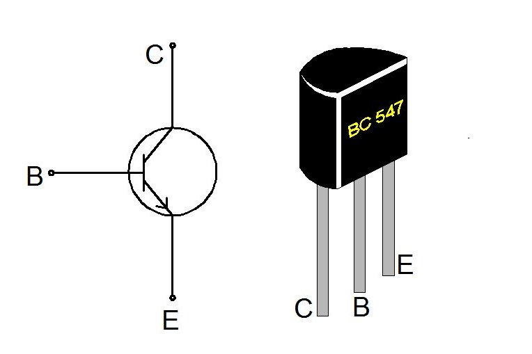
- BC547 TRANSISTOR

BC547 is an NPN bi-polar junction transistor. A transistor, stands for transfer of resistance, is commonly used to amplify current. A small current at its base controls a larger current at collector & emitter terminals.
BC547 is mainly used for amplification and switching purposes. It has a maximum current gain of 800. Its equivalent transistors are BC548 and BC549. data sheet