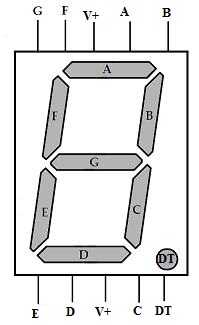
7-segment display
Overview
The 7 or 8-segment display are a number of LEDs
 Source:
https://www.jameco.com/jameco/workshop/techtip/working-with-seven-segment-displays.html
Source:
https://www.jameco.com/jameco/workshop/techtip/working-with-seven-segment-displays.html
You can control them as 7 separate LEDs But this is quite complexe "just" to display a digit. So there is another way to make the display is using a SHIFT REGISTER
Shift Register
SNx4HC595 8-Bit Shift Registers With 3-State Output Registers
The 74HC595 consists of an 8−bit shift register and a storage register with three−state parallel outputs. It converts serial input into parallel output so that you can save IO ports of an MCU. The 74HC595 is widely used to indicate multipath LEDs and drive multi-bit segment displays. "Three-state" mentioned above refers to the fact that you can set the output pins as either high, low or high impedance. With data latching, the instant output will not be affected during the shifting; with data output, you can cascade 74HC595s more easily. Compatible with low voltage TTL circuit, 74HC595 can transform serial input of 8-bit data into parallel output of 8-bit data. So it is often used to extend GPIO for embedded system and drive low power devices.
Features
- 8-bit, Serial In – Parallel out Shift register
- Operating Voltage: 2V to 6V
- Power Consumption: 80uA
- Output source/sink current: 35mA
- Output Voltage is equal to Operating voltage
- Minimum high-level Input Voltage: 3.15V @(Vcc=4.5V)
- Maximum low-level Input Voltage: 1.35V @(Vcc=4.5V)
- Can be easily cascaded with more IC to get more outputs
- Maximum Clock Frequency: 25Mhz @4.5V
- Available in 16-pin PDIP, GDIP, PDSO packages
Pinout

Pins of 74HC595 and their functions:
- Q0-Q7: 8-bit parallel data output pins, able to control 8 LEDs or 8 pins of 7-segment display directly.
- Q7’ - QH’: Series output pin, connected to DS of another 74HC595 to connect multiple 74HC595s in series
- MR - SRCLR : Reset pin, active at low level; here it is directly connected to 5V.
- SH: Time sequence input of shift register. On the rising edge, the data in shift register moves successively one bit, i.e. data in Q1 moves to Q2, and so forth. While on the falling edge, the data in shift register remain unchanged.
- ST: Time sequence input of storage register. On the rising edge, data in the shift register moves into memory register.
- OE - CE : Output enable pin, active at low level, connected to GND.
- Ds - SER : Serial data input pin
- VCC: Positive supply voltage
- GND: Ground
How it works

How to Use a 74HC595 IC
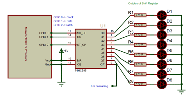
The 74HC595 shift register is commonly used with microcontrollers or microprocessors to expand the GIPO functionalities. It requires only 3 pins connected to the MCU, which are Clock, Data and Latch. It has a wide operating voltage from 2V to 6V. An application circuit of the IC is shown below:
Circuit
Connect
- ST_CP to Raspberry Pi GPIO1,
- SH_CP to GPIO2,
- DS to GPIO0.

Input data in DS pin to the shift register when SH_CP (the clock input of the shift register) is at the rising edge, and to the memory register when ST_CP (the clock input of the memory) is at the rising edge. Then you can control the states of SH_CP and ST_CP via Raspberry Pi GPIO to transform serial input data into parallel output data so as to save Raspberry Pi GPIOs.

code sample : Dice
Now you should see a number flashing between 0 and 6 quickly on the segment display. Press the button on the breadboard, and the display will statically display a random number between 0 and 6 for 2 seconds and then circularly flash randomly between 0 and 6 again.
#!/usr/bin/env python
import RPi.GPIO as GPIO
import time

SDI   = 11
RCLK  = 12
SRCLK = 13

segCode = [0x3f,0x06,0x5b,0x4f,0x66,0x6d,0x7d,0x07,0x7f,0x6f,0x77,0x7c,0x39,0x5e,0x79,0x71,0x80]

def print_msg():
    print 'Program is running...'
    print 'Please press Ctrl+C to end the program...'

def setup():
    GPIO.setmode(GPIO.BOARD)    #Number GPIOs by its physical location
    GPIO.setup(SDI, GPIO.OUT)
    GPIO.setup(RCLK, GPIO.OUT)
    GPIO.setup(SRCLK, GPIO.OUT)
    GPIO.output(SDI, GPIO.LOW)
    GPIO.output(RCLK, GPIO.LOW)
    GPIO.output(SRCLK, GPIO.LOW)

def hc595_shift(dat):
    for bit in range(0, 8):
        GPIO.output(SDI, 0x80 & (dat << bit))
        GPIO.output(SRCLK, GPIO.HIGH)
        time.sleep(0.001)
        GPIO.output(SRCLK, GPIO.LOW)
    GPIO.output(RCLK, GPIO.HIGH)
    time.sleep(0.001)
    GPIO.output(RCLK, GPIO.LOW)

def loop():
    while True:
        for i in range(0, len(segCode)):
            hc595_shift(segCode[i])
            time.sleep(0.5)

def destroy():   #When program ending, the function is executed.
    GPIO.cleanup()

if __name__ == '__main__': #Program starting from here
    print_msg()
    setup()
    try:
        loop()
    except KeyboardInterrupt:
        destroy()